
Alternating current:An electric current whose magnitude varies continuously with time and changes its direction periodically, is called an alternating current.
Alternating voltage:The voltage whose magnitude varies continuously with time and changes its direction periodically, is called an alternating voltage.
Impedance: It is the measure of the opposition that a circuit offers to a current when a alternating voltage is applied. In quantitative terms, it is the complex ratio of the voltage to the current in an alternating current (AC) circuit.
Admittance:It is the reciprocal of impedance.
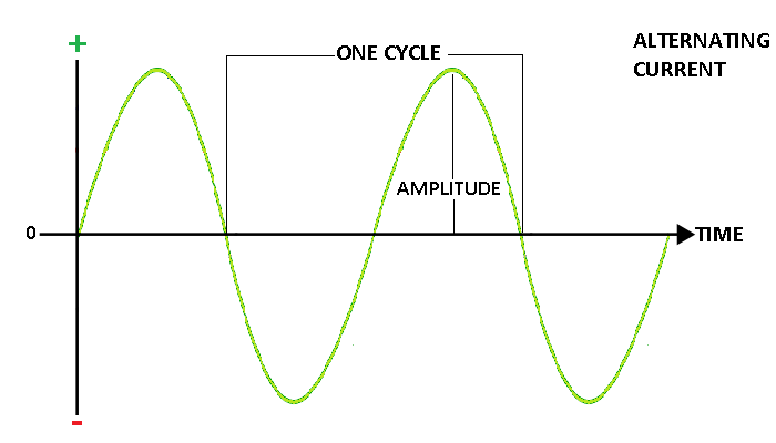
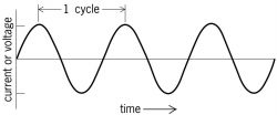
Cycle of alternating voltage and current:
The variation of voltage or current from zero to maximum in one direction,through zero to maximum in the opposite direction and back to zero again is called one cycle of voltage or current.
OR
The part of wave which is repeated again and again is called one cycle.
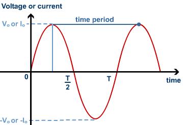
Time Period of alternating voltage or current:
The time taken by the alternating voltage or current to complete one cycle of its variations is called its periodic time or time period (T).
Frequency of alternating voltage or current:
The number of cycles completed by alternating voltage or current in one second is called as the frequency of alternating voltage or current.It’s unit is cycles/second or Hertz (Hz).
Phase:
Although the frequency of alternating current and alternating emf is same but it is not necessary that the alternating current and alternating emf may become maximum and minimum simultaneously. Generally, when current is maximum, emf is not maximum and vice versa. In some cases the current attains its peak value after the e.m.f has done so, the current is then said to lag behind the e.m.f. In some other cases, the current attains the maximum value, before the emf does so, the current is then said to lead the emf. This lead or lag is the phase difference between the emf (voltage) and current in A.c. circuits and is represented by  . Thus, if the emf (or Voltage) in A.c. is represented by
. Thus, if the emf (or Voltage) in A.c. is represented byV = Vo sin  t
t
tI = Io sin( t +
t +  )
)
t + )The phase difference may be positive,negative or zero according to the current lags,leads or in phase with the voltage.
Definition of phase:The phase of the wave is defined as the distance between the first zero-crossing and the point in space defined as the origin.
Average or mean value of alternating current or voltage:
The average value of alternating current over any half cycle is defined as that value of steady direct current which would send the same amount of charge through a circuit in half time period as is sent by the a.c. through the same circuit in the same time.
Here same circuit means both circuit should have same value of resistances.
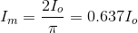
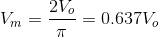
The average value of a.c. over positive half cycle is 63.70% of the peak value of a.c.
The average value of alternating voltage or current over one complete cycle is zero.
Root mean square value (RMS value) of alternating current:
It is defined as that value of steady current which would generate the same amount of heat in a given resistance in a given time as is done by the a.c. when passed through the same resistance for the same time.
RMS value is also known as virtual or effective value.
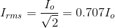
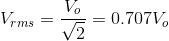
The rms value of a.c. is 0.707 times the peak value of a.c. or 70.7% of the peak value of a.c.
When we say that alternating potential difference between the supply mains of a house hold power line is 220V,it means that the rms potential difference is 220V. Therefore,peak value is  .
.
.Note: If d.c. ammeter , d.c. voltmeter are connected in a.c. circuit then they will record average value of a.c. over full cycle which is zero.Hence shows no deflections.
Phasor diagram:
A diagram representing alternating current and alternating voltage (of same frequency) as vectors (phasors) with the phase angle between them is called a phasor diagram.
The phase difference between current and voltage depends upon the nature of circuit elements i.e circuit consisting of resistor or an inductor or a capacitor or a combination of these.
Types of a.c. circuits:
-
R circuit
-
L circuit
-
C circuit
-
RL circuit
-
RC circuit
-
RLC circuit
1. A.c. circuit containing pure resistance:
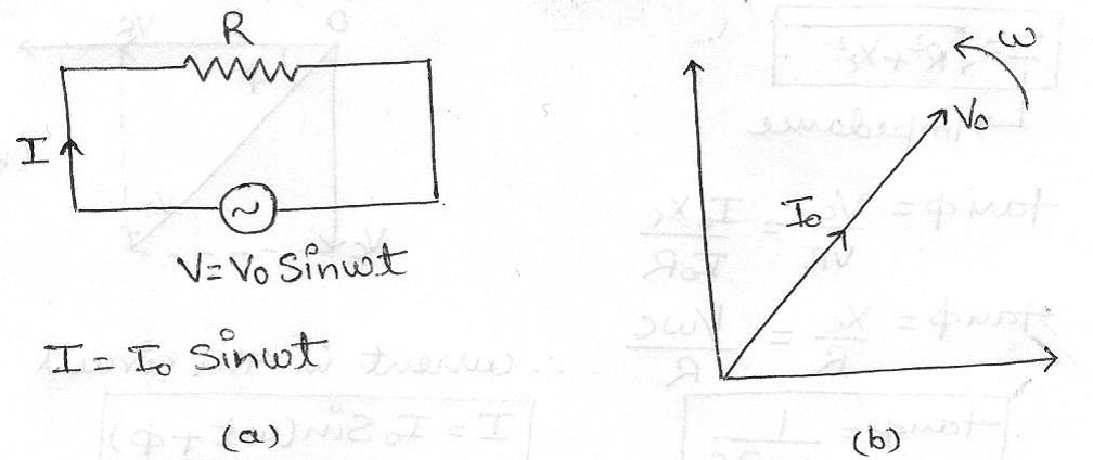
Applied e.m.f, V = Vo Sin t
t
tCurrent in the circuit, I = Io Sin t
t
tIo = Vo/R
where,Io & Vo are the peak value of current and voltage respectively.
The voltage and current are in the same phase i.e phase angle is 0°.
Figure (a) shows the circuit and Figure (b) shows its phasor diagram.
2. A.c. circuit containing pure inductance:
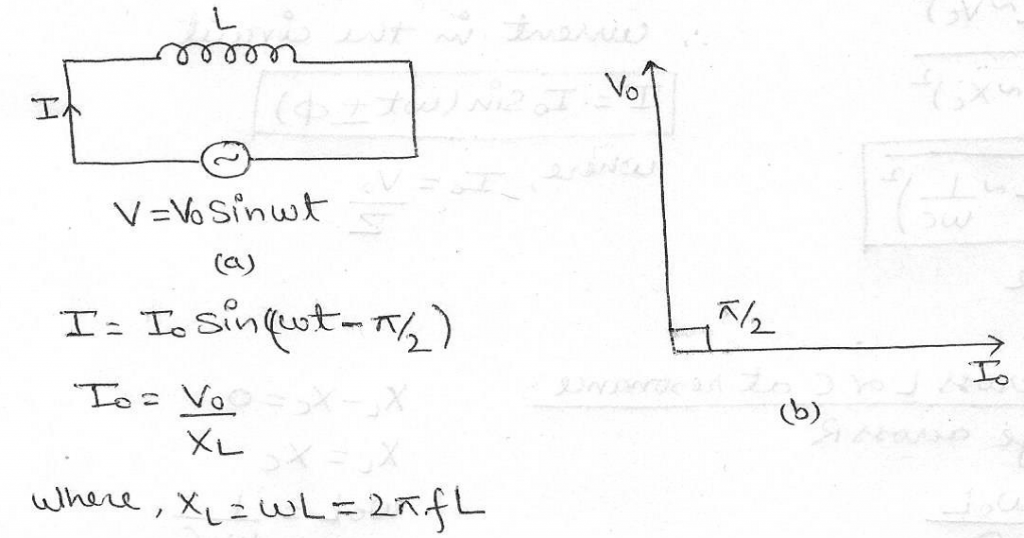
Figure (a) shows the circuit and Figure (b) shows its phasor diagram.
The current always lags behind the voltage by 90° or we can also say that voltage leads the current by a phase angle of 90°.
Inductive reactance: It is an opposition to the change of current through an inductor element.Inductive Reactance is given the symbol  in Ohms.
in Ohms.

Variation of Inductive reactance with frequency:
3. A.c. circuit containing pure capacitance:

Figure (a) shows the circuit and Figure (b) shows its phasor diagram.
The current always leads the voltage by 90° or we can also say that voltage lags behind the current by a phase angle of 90°.
Capacitive reactance:As the capacitor charges or discharges, a current flows through it which is restricted by the internal resistance of the capacitor. This internal resistance is commonly known as Capacitive Reactance and is given the symbol  in Ohms.
in Ohms.
Variation of Capacitive reactance with frequency:
4. A.c. circuit containing resistor and inductor (R-L circuit):
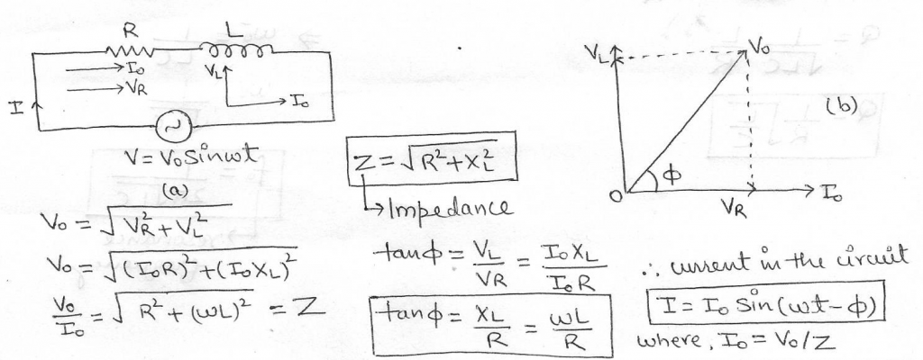
Figure (a) shows the circuit and Figure (b) shows its phasor diagram.
5. A.c. circuit containing resistor and capacitor (R-C circuit):
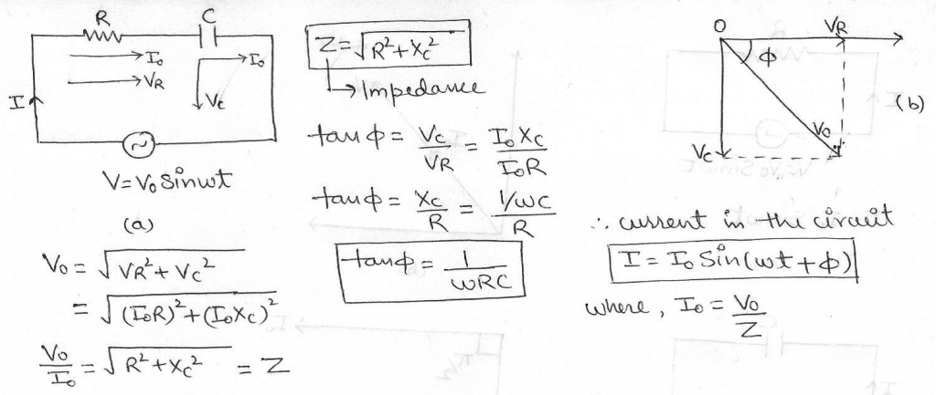
Figure (a) shows the circuit and Figure (b) shows its phasor diagram.
6. A.c. circuit containing resistor,capacitor and inductor (R-L-C circuit):
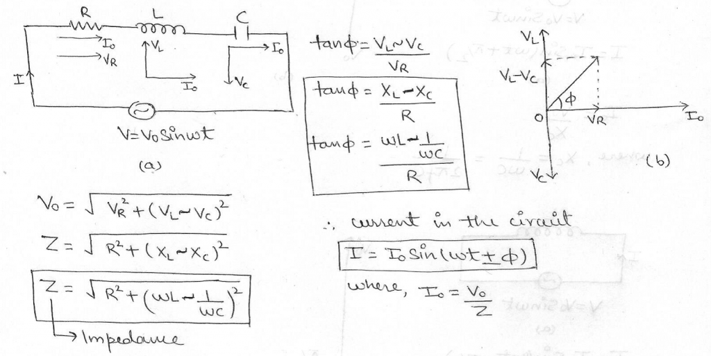
Figure (a) shows the circuit and Figure (b) shows its phasor diagram.
Note:
-
When
>
, then tan
is positive i.e.
is positive.The alternating emf V leads the current I by a phase angle
.The a.c. circuit is then inductance dominated circuit.
-
When
<
, then tan
is negative i.e.
is negative.The alternating emf V lags behind the current I by a phase angle
.The a.c. circuit is then capacitance dominated circuit.
-
When
=
, then tan
is zero i.e.
is zero.The alternating emf V and current I are in phase.The a.c. circuit is then purely resistive.
Resonance:
1. Series Resonant circuit:
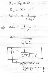
The series RLC circuit is said to be in resonance when the imaginary parts of impedances or admittances of circuit elements cancel each other i.e. reactance component ( –
–  ) of impedance is zero.
– ) of impedance is zero.The frequency at which the impedance of the circuit becomes minimum and current becomes maximum,is called resonance frequency of the circuit.
The peak value of amplitude falls off with increase in the value of resistance R i.e. Higher the value of ohmic resistance present,lesser the amplitude in the state of resonance.
A series resonant circuit gives voltage amplification. Hence it is also called as voltage resonant circuit.
2. Parallel Resonant circuit:
The current in the parallel resonant circuit is minimum (i.e. zero) when the frequency (f) of the applied alternating voltage becomes equal to the resonant frequency.
Quality factor and sharpness of resonance:
The current versus frequency curve is quite flat for a larger value of resistance and becomes more and more sharp as the value of the resistance is decreased.
The sharpness or selectivity of a resonance circuit is measured by Q-factor.
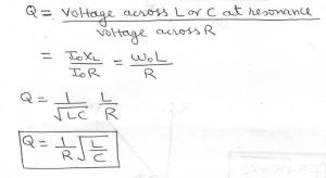
Q-factor (Quality factor) of series resonant circuit is defined as the ratio of the voltage developed across the inductance or capacitance at resonance to the impressed voltage (which is the voltage applied across R).
-
Q is a number.
-
Q factor is also called voltage amplification factor.
-
Q factor of RLC series circuit will be large i.e. the circuit will have more sharpness if R is low or L is large or C is low.
-
The electronic circuits with high Q-factor would respond to a very narrow range of frequencies and vice versa.
Power in an a.c. circuit:
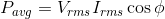
Power is defined as the rate of doing work in d.c. circuits and is given by the product of voltage and current.This definition of power cannot be used for calculating power in a.c. circuits because in a.c. circuits both V and I continuously vary.So for a.c. circuits,we calculate the average power by defining the instantaneous power of the circuit.

Average power is also known as true power.
The product (Vrms) (Irms) is known as the apparent power or virtual power.
Cos is known as Power factor.
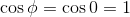
is known as Power factor.1. Average power in the circuit containing Resistance R only:


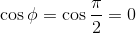
2. Average power in the circuit containing Capacitor C only or Inductor L only:


3. Average power in the series RLC circuit at resonance:


4. Average power in the Series RLC or RC or RL circuits:
Cos is calculated from impedance triangle.
is calculated from impedance triangle.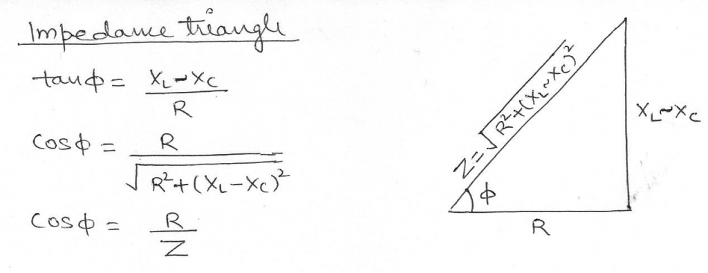
Wattless current:
If the resistance of an a.c. circuit is zero,although current flows in the circuit but the average power consumed in the circuit remains zero i.e. there is no dissipation of energy in the circuit.The current in such a circuit is called wattless current.
Advantages of alternating current over direct current:
-
A.C. can be obtained over a wide range of voltages.
-
The generation,transmission and distribution of a.c. is economical than that of d.c.
-
A.C. is easily convertible into d.c. by using rectifiers.
-
The cost in a.c. transmission is low and energy losses are minimised.
-
A.C. equipments such as electric motors,etc are more durable and convenient as compared to d.c. equipments.
-
A.c. can be better controlled without any loss of electric power.(e.g. by using a choke coil)
Disadvantages of alternating current over direct current:
-
A.C. is more dangerous as compared to d.c.
-
A.C. is not available in pure frequency.It contains higher harmonics.
-
For electroplating,electrotyping only d.c. can be used and not a.c.