
Electromagnetic Induction
Contents
hide
Electromagnetic induction is the phenomenon of production of electric field with the help of varying magnetic field.
Magnetic Flux and Magnetic Flux Density
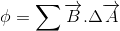
Magnetic flux (φ) through any surface is defined as the number of magnetic lines of force crossing through that surface.
the magnetic flux (φ) through the surface is defined as
(i) When θ = 0°, i.e. uniform magnetic field is acting perpendicular to the plane of the surface, then
= BA cos 0 or = BA = maximum
Thus, magnetic flux through a given surface is maximum i.e. maximum number of magnetic lines of force passes through the given surface when θ = 0°
(ii) When θ = 90°, i.e. uniform magnetic field is along the surface then
= BA cos 90° = 0
Thus, the magnetic flux through a given surface is zero when θ = 90°.
Note:
-
Equation
holds good only if the magnetic field is uniform over the surface.
-
If the magnetic field
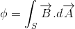
varies,then the surface is divided into number of area elements,each of which has area small enough so that magnetic field is constant through each of the areas.Let
be the area of a small element,then the magnetic flux through the elements is given by
therefore,the total magnetic flux through the surface is given by

or
Magnetic flux density or strength of Magnetic field or Magnetic Induction (B):
Magnetic flux density (B) is defined as the magnetic flux (associated normally) per unit area.

Units of Magnetic flux
In SI, magnetic flux is measured in weber (Wb).
1 weber = 1 tesla × 1 metre²
In c.g.s. ,unit of magnetic flux is maxwell.
1 maxwell = 10-8 weber
Faraday’s Experiments
Experiment 1
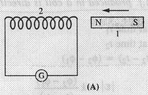
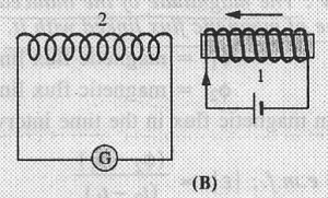 The apparatus used by Faraday consisted of a coil with a galvanometer and either a bar magnet (figure A) or an electromagnet (figure B)
Faraday performed the experiment and observed that
(i) when the bar magnet or electromagnet was at rest, the galvanometer showed no deflection.
(ii) when the bar magnet or electromagnet moved towards the coil 2, galvanometer showed deflection in one direction. Thus, there was flow of current in coil 2.
(iii) when the bar magnet or electromagnet moved away from the coil 2, galvanometer again showed the deflection but now in the opposite direction.Thus, there was flow of current in the coil 2 but in the opposite direction.
(iv) the deflection of the galvanometer was large if the bar magnet or electromagnet moved rapidly towards or away from the coil 2.
Faraday concluded that
(a) whenever there is a relative motion between a coil and the magnet,induced current flows through the coil.
(b) the large induced emf or current is produced in the coil if the relative motion between the magnet and the coil is large.
Experiment 2

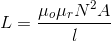
Two coils of insulated copper wire were wound on a wooden core as shown in figure . Coils were not connected physically with one another. One coil was connected to a battery through a key (K). This coil was called primary coil(P).The second coil placed near the first coil was connected to a sensitive galvanometer.This coil was called secondary coil(S).
Faraday performed the experiment and observed that :
(a) when key was pressed, the galvanometer in the secondary circuit showed a momentary deflection and then returned to zero.
(b) when the key was released, the galvanometer in the secondary circuit showed a momentary deflection but in the opposite direction and then returned to zero.
Faraday changed the wooden rod and used an iron rod. The galvanometer showed larger deflections on opening and closing of the key.
Explanation: When the key is closed or opened, current in the primary coil begins to increase or decrease respectively. This leads to the production of changing magnetic field or flux around the primary coil. Since secondary coil is very close to the primary coil, so changing magnetic flux is also linked with the secondary coil. Changing magnetic flux linked with the secondary coil causes the induced e.m.f. or current in it till the current in the primary coil becomes constant as shown by the deflection of the galvanometer.
Faraday concluded that an induced e.m.f. or current is produced in a coil when varying current flows through a neighbouring coil.
Faraday’s First law of Electromagnetic Induction
This law states that whenever magnetic flux linking with a coil changes, an induced e.m.f. is produced in the coil. This induced emf lasts so long as the change in magnetic flux continues.
Faraday’s Second law of Electromagnetic Induction
This law states that the magnitude of the induced e.m.f. (ε) produced in a coil is directly proportional to the rate of change of magnetic flux linked with it.
φ1 = flux linked with circuit at t = t1
φ2 = flux linked with circuit at t = t2
Therfore, induced e.m.f


If the closed circuit( say a coil) has N number of turns,then
 Average induced e.m.f.
where, N is the number of turns of the coil and φ is the magnetic flux linked.

 Instantaneous induced e.m.f
If the closed circuit( say a coil) has N number of turns,then
 Instantaneous induced e.m.f
Let,R is the resistance of the circuit
then the induced current is
i = ε/R

Charge flows through the circuit in time Δt
Δq = i Δt
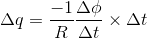

Note: induced e.m.f. and current are inversely proportinal to Δt while Δq is independent of Δt i.e. the charge flow through the circuit depends only upon the change in flux,not the time taken to change in it.
Lenz’ Law
The direction of induced e.m.f. is such that it opposes the cause which produces it.
OR
The direction of induced current in the circuit is always such that it opposes the cause which is responsible for its production.

Consider a closed coil connected to a galvanometer. Let a bar magnet with its North pole face the coil (Figure A). When the bar magnet moves toward the coil, the magnetic flux linked with it goes on increasing and hence induced e.m.f is produced in the coil. Due to this induced e.m.f., current flows through the coil and galvanometer shows deflection.
According to Lenz’ law, the direction of induced e.m.f is such that it opposes the cause (i.e. motion of the magnet) which produces it. To oppose the cause (motion of the magnet), the upper face of the coil acquires North polarity. The north pole of the magnet and the north pole of the coil repel each other. To move the magnet towards the coil,mechanical work has to be done to over come the force of repulsion between the north poles. This mechanical work done is converted into electrical energy.
Similarly, when the magnet moves away from the coil (Figure B), the upper face of the coil acquires South polarity. In this case, the induced e.m.f. will oppose the out ward motion (cause) of the magnet. Again mechanical work has to be done to overcome the force of attraction between North pole of the magnet and South pole of the coil. This work done is converted into electrical energy.
According to law of conservation of energy, energy can neither be created nor destroyed but changes from one form to another.
Thus, Lenz’ law follow the law of conservation of energy.
Fleming’s Right Hand Rule

It is also known as generator rule.
According to this rule
Direction of Field –> along the first finger
Direction of Motion –> along the thumb
Direction of induced e.m.f. or current –> along the middle finger
Methods of Producing Induced e.m.f.
From Faraday’s Law, induced e.m.f. is given by,

This shows that e.m.f. ε depends upon number of turns N and rate of change of magnetic flux (φ) Since magnetic flux, φ= BA cosθ.
So, magnetic flux can be changed by
(i) changing the intensity of the magnetic field (B)
(ii) changing the orientation (θ) of the coil with respect to the magnetic field.
(iii) changing the area of the closed circuit (A).
Motional e.m.f.
Induced e.m.f. produced by changing the area of a closed circuit by the movement of the circuit or part of it through a uniform magnetic field is known as motional e.m.f.
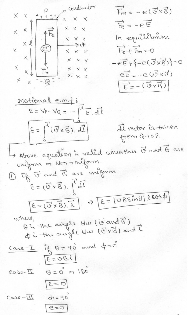
In Case II & III,conductors do not cut the magnetic field lines.
Force Required to Pull a Rod or Conductor Out of the Magnetic Field

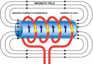
Eddy Currents
The induced circulating currents produced in a metal itself due to change in magnetic flux linked with the metal are called eddy currents.
These currents were discovered by Foucault, so they are also known as Foucault Currents.
The direction of eddy currents is given by Lenz’ law.
Undesirable Effects of Eddy Currents :
(i) The production of eddy currents in a metallic block leads to the loss of electric energy in the form of heat.
(ii) The heat produced due to eddy currents breaks the insulation used in the electrical machine or appliance.
(iii) Eddy currents may cause unwanted dampening effect.
Eddy currents can be minimized by using lamination. Lamination are the thin sheets which are electrically insulated from one another.
Applications of Eddy currents:
1. Induction Furnace. Induction furnace is based on the heating effect of eddy currents.
2. Speedometer. Speedometer is a device used to measure the instantaneous speed of a vehicle.
3. Dead beat galvanometer.
4. Electromagnetic Brakes. A strong magnetic field is applied across the metallic drum rotating with the axle of the electric train. Thus large eddy currents are produced in the metallic drum. These currents oppose the motion of the drum and hence the axle of the train which ultimately makes the train come to rest.
5. Diathermy. Eddy currents are used for the localised heating of tissues in human body. This type of treatment is called diathermy.
6. Energy meters. Concept of eddy currents is used in energy meters to record the consumption of electricity.
Self Induction
Self induction is the property of a coil by virtue of which it opposes the growth or decay of the current flowing through it.
The property of the coil which opposes the growth or decay of the current is called Self Induction.
Self induction is also known as Inertia of electricity as it opposes the growth or decay of the current in the circuit.
Let I be the current flowing through a coil then the magnetic flux (φ) linked with the coil is found to be proportional to the strength of the current (I) i.e.


where L is the constant of proportionality and is known as Co-efficient of self induction or self inductance.
Co-efficient of self induction of a coil is defined as the induced e.m.f. produced in the coil through which the rate of decrease of current is unity.
According to faraday’s law of electromagnetic induction

then e.m.f induced is

-
SI Unit of self inductance is henry (H)
-
Spark is produced in the electric switch when the light is switched off.
-
When the circuit is switched off, the current in the circuit begins to decrease rapidly. As a result of this, a large induced e.m.f. is set up across the switch contacts which tries to maintain the current. This e.m.f. is sufficient to break down the insulation of the air between the switch contacts and hence spark is produced.
Inductor : An element of an electric circuit like a tightly wound coil of insulated wire which opposes the change in current flowing through it is called an inductor. The symbol of an inductor in an electric circuit is shown as follows :
-
An ideal Inductor has high value of self inductance and zero ohmic resistance.
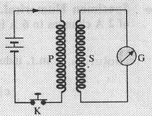
Self Inductance of a Solenoid

Self inductance of an air cored solenoid (L) depends on
(i) the total number of turns (N) of the solenoid and
(ii) the length (l) of the solenoid and
(iii) the area of cross-section (A) of the solenoid.
Self Inductance of a Solenoid Wound on Magnetic Material
When a solenoid is wound on a rod of magnetic material of permeability,the self inductance of the solenoid is given by
Self Inductance of Combination of Coils
(A) Coils in Series.

(B) Coils in Parallel.

Energy stored in an Inductor
 where,Io is the maximum value of current through the inductor.
The work done in increasing the current flowing through the inductor is stored as the potential energy (U) in its magnetic field.
The energy stored in the inductor or coil is known as magnetic energy.
Mutual Induction
Mutual Induction is the phenomenon of inducing e.m.f in a coil due to the rate of change of current in a nearby coil.
Consider a coil connected to a battery through a key (K). This coil is called Primary coil (P). Another coil placed near the primary coil and connected to the galvanometer is called secondary coil (S). When key (K) is pressed, galvanometer shows a deflection.
When key (K) is pressed, current through P begins to increase. As a result of this, magnetic field around P increases, so magnetic flux linking with secondary coil also changes. The induced e.m.f is produced in the secondary coil due to the change in magnetic flux linking with the coil. Hence the current flows through the secondary coil which is indicated by the deflection of the galvanometer. This phenomenon of inducing e.m.f is called mutual induction.
It is known that the magnetic flux linking with the secondary coil is directly pr
oportional to the current flowing through the primary coil i.e.


According to faraday’s law of electromagnetic induction

then e.m.f induced in secondary winding is


where M is a constant called as Coefficient of Mutual Induction or Mutual Inductance
Mutual inductance of the two coils or circuits can be defined as the magnetic flux linked with the secondary coil due to the flow of unit current in the primary coil.
OR
Mutual inductance of two coils can be defined as the induced e.m.f produced in the secondary coil due to unit rate of decrease of current in the primary coil.
-
SI unit of mutual inductance is henry (H).
Mutual Inductance of Two Long Co-axial Solenoids

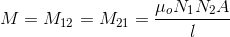
Factors on which Mutual Inductance depends:
The value of mutual inductance of two coils depends upon :
(i) geometry of two coils i.e. size, shape and number of turns (N1 and N2) of the coils.
(ii) nature of the material on which the two coils are wound.
(iii) the distance between the two coils.
(iv) the relative placement of two coils.