
Rectifier:
It is a device which converts ac voltage to dc voltage.
Principle:
Principle:
Rectifier is based on the fact that, a forward bias p-n junction conducts and a reverse bias p-n junction does not conduct.
Rectifiers are of three types:
1. Half wave rectifier
2. Full wave rectifier
3. Bridge rectifier
3. Bridge rectifier
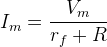
Half-wave rectifier:
.gif)
- The rectifier which converts only one half of a.c. into d.c. is called half wave rectifier.
- It is the simplest type of rectifier, which is made with just one diode.
- When the voltage of the alternating current is positive, the diode becomes forward-biased and current flows through it.
- When the voltage is negative, the diode is reverse-biased and the current stops.
- The result is a cropped copy of the alternating current waveform with only positive voltage.This pulsating direct current is adequate for some components, but others require a more steady current.
 |
| Half wave rectifier |
 |
| Input and Output voltages of half wave rectifier |
- Peak value of current is
.gif)
.gif)
where, rf is the forward diode resistance, R is the load resistance and Vm is the peak value of the alternating voltage.
- rms value of current is
.gif)
- dc value of current is
.gif)
- Peak inverse voltage is
.gif)
.gif)
.gif)
- dc value of voltage is
.gif)
- Ripple frequency
.gif)
.gif)
.gif)
(If input voltage Vi frequency is 50 Hz)
Disadvantages:
b>
1. Since output signal is discontinuous,so the efficiency of half wave rectifier is small.
2. The output is not pure d.c. but it is fluctuating ( or pulsating d.c.) which contains a.c. components or ripples also.
1. Since output signal is discontinuous,so the efficiency of half wave rectifier is small.
2. The output is not pure d.c. but it is fluctuating ( or pulsating d.c.) which contains a.c. components or ripples also.
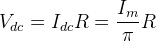
Full-wave rectifier:
- This rectifier is essentially made of two half-wave rectifiers, and can be made with two diodes and an earthed centre tap on the transformer. The centre tap allows the circuit to be completed because current cannot flow through the other diode.
- When the voltage of the alternating current is positive, one of the diodes become forward biased whereas the other gets reverse biased. Hence, current flows through the forward biased diode.
- When the voltage of the alternating current is negative, the previous reverse biased diode becomes forward biased whereas the other gets reverse biased. Hence, current flows through the forward biased diode.
- Thus, current flows at least through one of the diodes at a time.
- Therefore, the result is still a pulsating direct current but with double the frequency.
- Since output is continuous, so its efficiency is more than that of the half wave rectifier.
- however,the output is again fluctuating which can be smoothened by using a filter circuit.
 |
Full wave rectifier |
 |
| Input and Output voltages of full wave rectifier |
- Peak value of current is
where, rf is the forward diode resistance, R is the load resistance and Vm is the peak value of the alternating voltage.
- rms value of current is
- dc value of current is
.gif)
- Peak inverse voltage is
.gif)
.gif)
.gif)
- dc value of voltage is
.gif)
- Ripple frequency
.gif)
.gif)
.gif)
(If input voltage Vi frequency is 50 Hz)
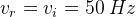
Bridge rectifier:
- A bridge rectifier makes use of four diodes in a bridge arrangement to achieve full-wave rectification.
- The main advantage of this bridge circuit is that it does not require a special centre tapped transformer, thereby reducing its size and cost.
- The single secondary winding is connected to one side of the diode bridge network and the load to the other side as shown below.
- The result is still a pulsating direct current but with double the frequency.
 |
| Bridge rectifier |
 |
| Fig.1 (For positive half cycle) |
 |
| Fig.2 (For negative half cycle) |
Working of bridge rectifiers (Fig.1 and Fig.2)
 |
| Input and Output voltages of bridge rectifier |
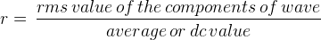
Ripple Factor
The ripple factor is a measure of purity of the dc output of a rectifier, and is defined as
.gif)
.gif)
.gif) ,
,.gif)
.gif)
.gif) ,
,.gif)
.gif)
.gif)
.gif)
For half wave rectifier,
.gif) ,
,.gif)
.gif)
r = 1.21
For full wave rectifier,
.gif) ,
,.gif)
r = 0.482
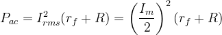
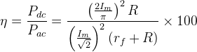
Rectification Efficiency:
The rectification efficiency tells us what percentage of total input ac power is converted into useful dc output power. Thus, rectification efficiency is defined as
.gif)
.gif)
.gif)
.gif) %
%
.gif) %
%
.gif) = 40.6 %
= 40.6 %
.gif)
.gif)
.gif) %
%
.gif) %
= 81.2 %
%
= 81.2 %
.gif)
For half wave rectifier,
dc power delivered to the load is
.gif)
Input ac power is
.gif)
Rectification efficiency
.gif) %
%.gif) %
%
If rf << R, maximum rectification efficiency ,
.gif) = 40.6 %
= 40.6 %For full wave rectifier,
dc power delivered to the load is
.gif)
Input ac power is
.gif)
Rectification efficiency
.gif) %
%.gif) %
%
If rf << R, maximum rectification efficiency ,
= 81.2 %
Light Emitting Diode (LED)
- It converts electrical energy into light energy
- It is a heavily doped p-n junction which under forward bias emits spontaneous radiation.
- The I-V characteristics of a LED is similar to that of Si junction diode. But the threshold voltages are much higher and slightly different for each colour. The reverse breakdown voltages of LEDs are very low, typically around 5 V.
- The semiconductor used for fabrication of visible LEDs must at least have a band gap of 1.8 eV.
- The compound semiconductor gallium arsenide phosphide (GaAsP) is used for making LEDs of different colours.
- GaAs is used for making infrared LED.
- The advantage of this device is its high power to light conversion efficiency.The efficiency is almost 50 times greater than a simple tungsten lamp.
- The symbol of a LED is shown in the figure.

Principle:
We know that a P-N junction can connect the absorbed light energy into its proportional electric current. The same process is reversed here. That is, the P-N junction emits light when energy is applied on it. This phenomenon is generally called electroluminance, which can be defined as the emission of light from a semi-conductor under the influence of an electric field. The charge carriers recombine in a forward P-N junction as the electrons cross from the N-region and recombine with the holes existing in the P-region. Free electrons are in the conduction band of energy levels, while holes are in the valence energy band. Thus the energy level of the holes will be lesser than the energy levels of the electrons. Some part of the energy must be dissipated in order to recombine the electrons and the holes. This energy is emitted in the form of heat and light.
Photodiode
- A photodiode is a special type p-n junction diode fabricated with a transparent window to allow light to fall on the diode.
- It is operated under reverse bias.
- When it is illuminated with light of photon energy greater than the energy gap of the semiconductor, electron-hole pairs are generated in near depletion region.
- The symbol of a photodiode is shown in the figure below.

Solar Cell
- It converts solar energy into electrical energy.
- A solar cell is basically a p-n junction which generates emf when solar radiation falls on the p-n junction.
- It works on the same principle (photovoltaic effect) as the photodiode, except that no external bias is applied and the junction area is kept large.
- The symbol of a photodiode is shown in the figure below.

<
/span>
Zener Diode
- It was invented by C. Zener.
- It is designed to operate under reverse bias in the breakdown region and is used as a voltage regulator.
- The symbol for Zener diode is shown in the figure.

Zener Diode as a Voltage Regulator
The circuit diagram for zener diode as a voltage regulator is shown in the figure below.

