
COMMUNICATION SYSTEM
The setup used for exchanging information between a sender and receiver is called communication system.
Information is specified as a measurable quantity in the technical description and the analytical treatment of the communication system.
A message can be
-
a sequence of distinct symbols or letters
-
single time varying quantity i.e. speech,music,etc.
-
many function of time and other variables i.e. light or colour of picture tube.
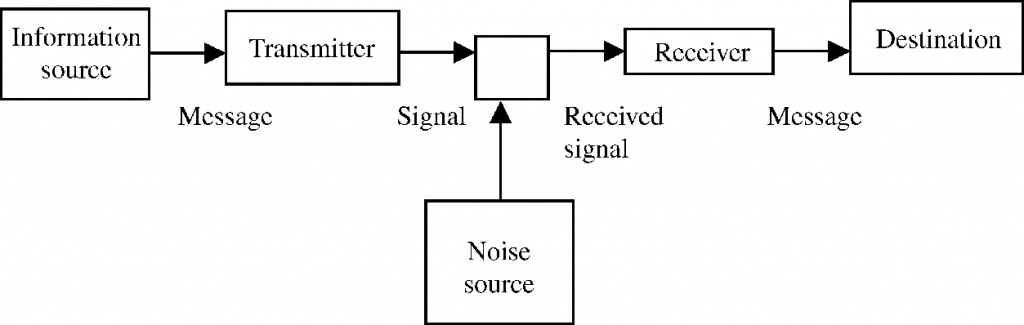
A communication system is composed of three basic units.
1. Transmitter
2. Transmission channel
3. Receiver
Transmitter: The part of communication system that transmits a message or signal over the channel to the receiver is called transmitter.
-
It is empowered with a transducer and an amplifier.
-
The function of transducer is to convert energy in one form to another.
-
Amplifier boosts up the power of the signal.
Transmission channel: The medium or the link, which transfer message signal from the transmitter to the receiver of communication channel.
Signals may be carried to the receiver in two ways:
• Through wires or cables
• By electromagnetic waves (wireless medium)
Receiver: The part of the communication system which pick up the information sent out by the , transmitter is called receiver.A receiver extracts the desired message signals from the received signals at the channel output.
Transducer:Transducer is a device which convert energy in one form to another. An electrical transducer converts some physical variable (pressure, displacement, force, temperature, etc) into corresponding variations in the electrical signal at its output.
Noise refers to the undesirable effects that tend to disturb the transmission and processing of message signals in a communication system.It may be of two types
-
External noise
-
Internal noise
Attenuation refers to the loss of strength of a signal while propagating through a medium.
Amplification is the process of increasing the amplitude and thereby the strength of a signal using an electronic circuit called the amplifier.
Range is the largest distance between a source and a destination up to which a signal is received with sufficient strength.
Bandwidth refers to the range over which the frequencies of a signal vary.
Signal
A processed information converted into electrical pulse for transmission is called a signal.
There are two forms of signal
1. Analog signal
2. Digital signal
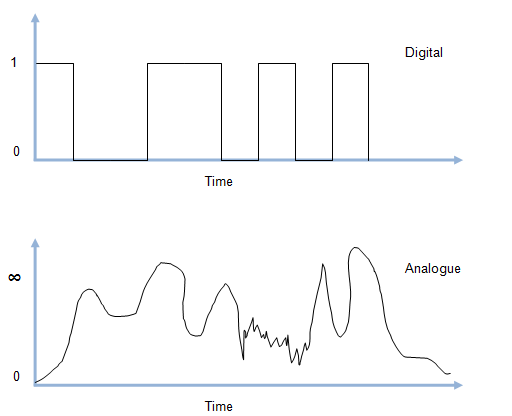
Analog signal : A signal, which is a continuous function of time.
Digital signal : A signal, which is a discontinuous function of time, which has only two levels (either low or high) is called a digital signal.
Transducer : A device which converts energy in one form to another is called a transducer.
Bandwidth of signals
The frequency range of a signals is called its bandwidth. Different types of signals require different ranges of frequencies for proper communication.
Modulation
The process of changing some characteristics e.g. amplitude, frequency or phase of carrier wave in accordance with instantaneous value of modulating signal is known as modulation.In modulation, a high frequency carrier wave is used to carry the information signal.
Need of Modulation
a). For efficient transmission and reception, the transmitting and receiving antenna must have a length equal to quarter wavelength of the audio signal.For example frequency of 15 kHz of audio signal, the length of the antenna comes out to be of the order of 5000 m. If we need to transmit such a signal directly, the size of the antenna will be very large and impossible to build.
b). The radiated power by an antenna is inversely proportional to the square of the wavelength. So, if we use high frequency signals, the power radiated will be increased.
c). Due to the fact that all audio signals from different sources possess frequencies in the same range i.e., 20 Hz to 20 kHz, an audio signal cannot be transmitted directly. It is because, the signals from different transmitters will get mixed up and the information will be lost.
Types of modulation
1. Amplitude modulation
2. Frequency modulation
3. Phase modulation
Amplitude Modulation
When the amplitude of carrier wave is varied in accordance with the amplitude of the audio frequency modulating signal,it is called amplitude modulation.
-
The amplitude of the carrier wave changes according to the intensity of the signal.
-
The amplitude variations of the carrier wave is at the signal frequency.
-
The frequency of amplitude modulated wave remains unchanged as that of the carrier wave.
Modulation factor:
It is the ratio of change of amplitude of carrier wave to the amplitude of normal carrier wave.
Modulation factor determines the strength and quality of the transmitted signal.The degree of modulation should never exceed 100%.
Frequency Modulation
When the frequency of carrier wave is varied in accordance with the instantaneous value of the modulating voltage,it is called frequency modulation.
Advantages and disadvantages of frequency modulation :
Advantages:
1. FM reception is quite immune to noise as compared to AM reception. Noise is a form of amplitude variations in the transmitted signal due to atmosphere, industries, etc. In FM receivers, the noise can be reduced by increasing the frequency deviation or by making use of amplitude limiter
s.
2. FM transmission is highly efficient as compared to AM transmission.
In FM transmission, all the transmitted power is useful; whereas in AM transmission, most of the power goes waste in the transmitted carrier, which contains no useful information.
3. Due to a large number of sidebands, FM transmission can be used for the stereo sound transmission.
Disadvantages:
1. The bandwidth in FM transmission is about 10 times as large as that needed in AM transmission. As a result, much wider frequency channel is required in FM transmission.
2. FM reception is limited to line-of-sight. Due to this, area of reception for FM is much smaller than that for AM.
3. FM transmitting and receiving equipments are very complex as compared to those employed in AM transmission.
Demodulation
The process of recovering the audio signal from the modulated wave is known as demodulation or detection.
Earth’s Atmosphere
The gaseous envelope surrounding the earth is called earth’s atmosphere.
Earth’s atmosphere mainly consists of nitrogen 78%, oxygen 21% along with a little portion of argon, carbon dioxide, water vapour, hydrocarbons, sulphur compounds and dust particles.
Earth’s atmosphere helps in the propagation of electromagnetic waves from one place to another place.
The various regions of earth’s atmosphere are as follows:
|
Regions of earth’s atmosphere
|
Description
|
|
Troposphere
|
|
|
Stratosphere
|
|
|
Mesophere
|
|
|
Ionosphere
|
|
LF = Low frequency
MF = Medium frequency
HF = High frequency
|
Name of the layer
|
Approximate height over earth’s surface
|
Exists during
|
Frequencies most affected
|
|
D
|
65-75 km
|
Day only
|
Reflects LF, absorbs MF and HF to some degree
|
|
E
|
100 km
|
Day only
|
Helps surface waves, reflects HF
|
|
F1
|
170-190 km
|
Day time, merges with F2 at night
|
Partially absorbs HF waves yet allowing them to reach F2.
|
|
F2
|
300 km at night, 250-400 km during day time
|
Day and night
|
Efficiently reflects HF waves, particularly at night
|
Radio waves
The electromagnetic waves of frequency ranging from a few kilohertz to few hundred megahertz are called radio waves.
Frequency range and wavelength range of radiowaves are given in the table.
|
S.No.
|
Frequency band
|
Frequency range
|
Wavelength
range
|
Main use
|
|
1.
|
Very-low frequency (VLF)
|
3 kHz to 30 kHz
|
10 km to 100 km
|
Long distance point to point communication
|
|
2.
|
Low frequency (LF)
|
30 kHz to’300 kHz
|
1 km to 10 km
|
Marine and navigational purpose
|
|
3.
|
Medium frequency (MF)
|
300 kHz to 3 MHz
|
100 m to 1 km
|
Marine and broadcasting purposes
|
|
4.
|
High frequency (HF)
|
3 MHz to 30 MHz
|
10 m to 100 m
|
Communications of all types
|
|
5.
|
Very high frequency (VHF)
|
30 MHz to 300 MHz
|
1 m to 10 m
|
T.V., Radar and air navigation
|
|
6.
|
Ultra-high frequency (UHF)
|
300 MHz to 3000 MHz
|
10 cm to 1 m
|
Radar and microwave communication
|
|
7.
|
Super-high frequency (SHF)
|
3 GHz to 30 GHz
|
1 cm to 10 cm
|
Radar, radio relays and navigation purposes
|
|
8.
|
Extremely high frequency(EHF)
|
30 GHz to 300 GHz
|
1 mm to 1 cm
|
optical fibre communication
|
Space communication or Propagation of electromagnetic Waves in Atmosphere
The term space communication refers to sending receiving and processing of information through space. There are three types of space communication :
-
Ground wave propagation
-
Sky wave propagation
-
Space wave propagation
Ground Wave Propagation
-
The radiowaves which travel through the atmosphere following the surface of the earth are called ground or surface wave and the propagation using such waves is called ground wave propagation or surface wave propagation.
-
These waves can travel around the curvature of the earth.
-
These waves can bend round
the corners of the objects on the earth,hence their intensity falls with distance.This is the reason that ground waves cannot go up to very long distances on ground.
-
Ground wave transmission becomes weaker as frequency increases,because of increased absorption of ground waves at higher frequency.
-
Ground wave transmission is optimum for local broadcasting using low and medium frequency range up to 2 MHz. Hence, it is also called medium wave propagation.
-
The maximum range of ground wave propagation depends on the frequency of the radiowaves and the power of the transmitter.
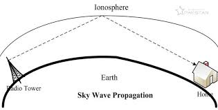
Sky Wave Propagation (Ionospheric Propogation)
-
Sky waves are the radiowaves with frequency between 2 MHz and 30 MHz.
-
Sky waves propagate through atmosphere and are reflected back by the ionosphere.Since these waves go from transmitter antenna to receiver antenna while travelling through sky,hence their propagation is called as sky wave propagation.
-
These waves can cover a distance of 4,000 km in a single reflection from the ionosphere.
-
This makes sky waves practically useful at medium and high frequencies for very long distance radio communication.
-
Critical frequency is that maximum frequency of radiowaves, which when sent normally towards the ionosphere, is reflected back to the earth.
-
Maximum usable frequency is that highest frequency of radiowaves which when sent at some angle towards the ionosphere,gets reflected from that and returns to the earth.
-
Radiowaves having frequency greater than the critical frequency will penetrate through the atmosphere and escape.
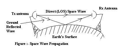
Space Wave Propagation (Tropospherical Propagation)
-
Space waves are the radiowaves of very high frequency (i.e. 30 MHz to 300 MHz).
-
These waves can travel through the atmosphere from the transmitter antenna to the receiver antenna either directly or after getting reflected from the ground or in the troposphere.Hence,their propagation of such waves is called space wave propagation or tropospherical propagation.
-
Space wave propagation is utilised in very high frequency bands (VHF: 30 MHz – 300 MHz), ultra high frequency bands (UHF)
and microwaves. -
Space wave propagation is suitable for line-of-sight (LOS) communication as well as satellite communication. This type of propagation is restricted by the line of sight distance and curvature of the earth.
-
Line of sight distance (LOS) is the distance between the transmitting antenna and the receiving antenna at which they are visible to each other. LOS distance is also known as the range of communication.
-
By increasing the height of the transmitting and receiving antennas, this range can be increased.
-
It has applications in TV transmission and radar communication.